


Guia de Luz Usinada CNC: Projetar, Materiais, e Processo de Fabricação Explicado
Um Guia de Luz usinado CNC não é simplesmente uma peça plástica transparente com superfície polida. É um componente óptico-mecânico no qual as propriedades do material, Acoplamento de luz, Condição da superfície, geometria, Estratégia de usinagem, e as condições de montagem influenciam o desempenho final da iluminação.
Na GD Prototipagem, we recommend evaluating a CNC Machined Light Guide as part of the complete lighting system rather than as an isolated CNC component. A part can meet dimensional tolerances and still fail optically because of excessive scattering, poor LED coupling, incorrect extraction features, or assembly-induced stress.
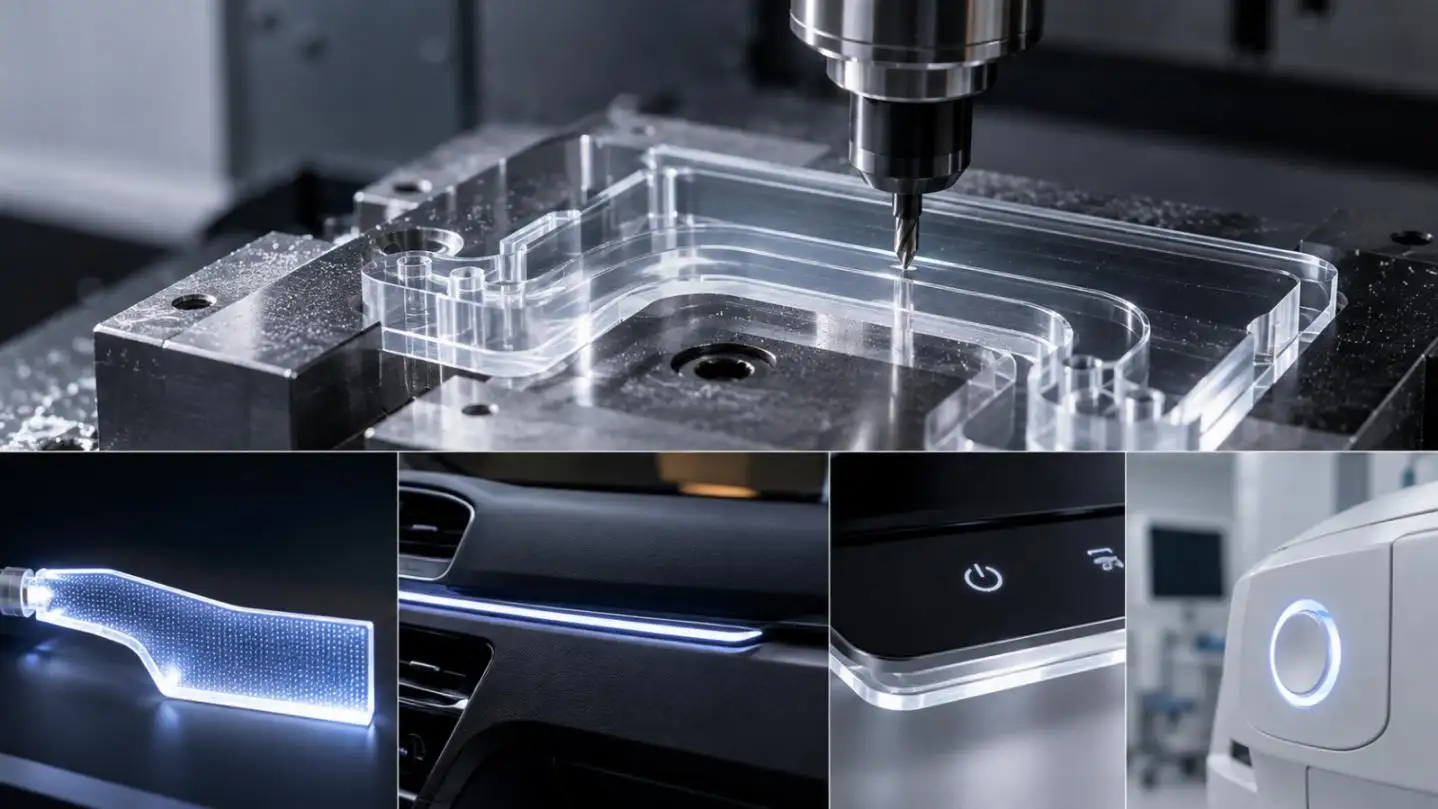
Why CNC Machined Light Guides Develop Hot Spots and Dark Areas
Two of the most common prototype problems are excessive brightness near the LED and insufficient light at the far end.
Typical causes include:
• LED beam angle not matched to the input geometry
• Excessive air gap between LED and light guide
• Machining marks on critical transport surfaces
• Extraction features that remove too much light near the source
• Uniform groove or dot density along a long light path
• Material absorption and accumulated scattering losses
For a long CNC Machined Light Guide, the available optical power decreases as light travels through the component. This is why extraction patterns are often graded rather than uniform.
LEDs are known to induce unwanted side effects (such as deformation) on certain light guides due to the high intensity of light they emit. In close proximity to an LED, it is recommended to apply less aggressive extraction. Further away from the LED, design trade-offs may include adjusting groove depth, feature density, pitch and/or geometry to mitigate the effect of reduced internal light.
How Light Travels Through a CNC Machined Light Guide
In a typical light guide, total internal reflection is used to confine light within a transparent structure.
The critical angle is defined as:
θ c =sin −1( n2/n1)
Onde (n_1) is the refractive index of the light guide and (n_2) is the refractive index of the surrounding material.
In practical manufacturing terms, this creates two different surface requirements.
Transport Surfaces
These surfaces should preserve light inside the CNC Machined Light Guide. Requirements may include:
•Low unintended surface scattering
• Controlled machining marks
• Minimal scratches and edge damage
• Appropriate polishing where required
• Good flatness or profile accuracy
Extraction Surfaces
These surfaces intentionally disturb TIR and redirect light outward through:
• Micro-grooves
• Dots
• Serrations
• Prismatic features
• Controlled textures
A common mistake is specifying the same surface finish for every face. Optical transport surfaces and light-extraction surfaces perform different functions and should be defined separately on the drawing.
PMMA vs. Polycarbonate for CNC Machined Light Guides
Material selection should be based on the operating environment as well as optical performance.
| Engineering Factor | PMMA | Policarbonato |
| Optical clarity | Typically very high | Bom, grade-dependent |
| Impact resistance | Moderado | Alto |
| Heat resistance | Moderado | Generally higher |
| UV performance | Often favorable | Grade/coating dependent |
| Usinagem CNC | Good with correct parameters | More sensitive to heat and stress |
| Typical use | Optical clarity, display and lighting prototypes | Mechanically demanding assemblies |
GD Prototyping recommends defining the actual material grade rather than specifying only "acrílico" ou "clear PC."
For a CNC Machined Light Guide, material selection should consider:
• Refractive index
• Luminous transmittance
• Haze
• UV exposure
• Operating temperature
• Chemical exposure
• Mechanical loading
• Required machining and polishing method
Material transmittance should not be treated as light-guide efficiency. A transparent sheet may have excellent transmission data while a finished component still performs poorly because of coupling losses, geometria, surface scattering, or extraction design.
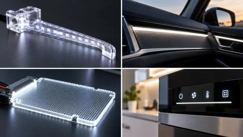
Usinagem CNC, Polimento, and Optical Surface Control
CNC machining is particularly useful during prototype and low-volume development because engineers can modify geometry without committing to injection-molding tooling.
Contudo, machining transparent polymers requires more than tight dimensional control.
Important process factors include:
• Cutting-tool sharpness and geometry
• Spindle speed and feed rate
• Heat generation
• Workholding pressure
• Tool-path direction
• Burr and chip control
• Post-machining polishing
Excessive heat can cause localized melting, stress, whitening, or poor edge quality. Over-clamping can introduce deformation or residual stress.
For optical parts, GD Prototyping treats dimensional accuracy and optical surface quality as separate requirements.
A tolerance such as ±0.05 mm does not define whether the surface is optically acceptable.
When Is Polishing Required?
Not every machined face requires polishing.
Polishing is normally considered when the surface must:
• Couple light efficiently
• Preserve TIR
• Minimize uncontrolled scattering
• Provide a clear cosmetic appearance
Em contraste, intentionally textured extraction regions should normally retain their designed geometry.
Possible finishing routes include mechanical polishing and other application-dependent optical finishing methods. The correct process depends on material, geometria, Acessibilidade, and the required surface specification.
Match the Light Guide to the LED and Housing
The performance of a CNC Machined Light Guide depends strongly on system integration.
Key variables include:
LED Coupling
Evaluate:
• Beam angle
• LED-to-guide distance
• Input-face dimensions
• Input-face curvature or profile
• Mechanical alignment tolerance
A small positional shift can change the amount and angular distribution of light entering the guide.
Reflectors and Diffusers
A reflector can redirect otherwise lost light, while a diffuser can improve perceived uniformity. These components should be evaluated together with the light guide instead of being added after optical problems appear.
Mechanical Mounting
Avoid concentrated clamping loads on transparent polymers. Excessive local stress can lead to:
• Optical distortion
• Stress birefringence
• Cracking
• Dimensional change
• Long-term creep
Thermal expansion should also be considered, particularly when the light guide is mounted inside metal housings.
How Should a CNC Machined Light Guide Be Inspected?
A professional inspection plan should separate mechanical and optical requirements.
| Inspection Area | Typical Items |
| Dimensional | Espessura, Perfil, Posição do buraco, insipidez |
| Superfície | Marcas de ferramentas, Arranhões, chips, waviness |
| Optical | Transmittance, haze, light distribution |
| Funcional | LED coupling, brightness uniformity |
| Assembléia | Ajuste, Gap, Alinhamento, mechanical stress |
Relevant optical-plastic test methods may include ISO 13468 for luminous transmittance and ISO 14782 or ASTM D1003 for haze. Optical drawings may also reference applicable ISO 10110 requirements when surface texture, imperfections, or other optical characteristics need formal definition.
The important point is consistency: measurement conditions such as LED current, distance, ambient conditions, and uniformity calculation should be defined before comparing prototypes or suppliers.
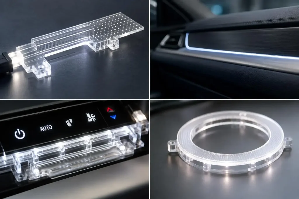
From CNC Prototype to Production
A CNC machined light guide can be very useful during the process of finalizing the optical design. It helps to evaluate varying materials, positions of the LEDs, extraction patterns and shapes of the housing. This helps in making a decision on the feasibility of production tooling.
A practical development sequence is:
Optical concept → CNC prototype → System testing → Design adjustment → Validation → Production-process decision
If you are developing a CNC Machined Light Guide, GD Prototyping can support the transition from CAD design to physical prototype while considering machining feasibility, Seleção de materiais, Requisitos de superfície, and inspection strategy.
Perguntas frequentes
Q1. Can GD Prototyping manufacture a CNC Machined Light Guide?
Sim. GD Prototyping provides CNC machining for engineering plastics and supports 3-axis, 4 eixos, e usinagem de 5 eixos. Light-guide projects should be reviewed for material, geometria, Superfícies ópticas, and finishing requirements before production.
Q2. What materials can GD Prototyping machine for light-guide prototypes?
GD Prototyping machines a range of engineering plastics, including PC. For a CNC Machined Light Guide, the exact optical-grade PMMA or PC specification should be confirmed during project review.
Q3. Does GD Prototyping support 5-axis machining for complex light-guide geometry?
Sim. A prototipagem GD suporta 3 eixos, 3 2-eixos, e fresagem completa de 5 eixos, which can reduce setups for complex contours, Superfícies inclinadas, and multi-face features.
Q4. Can GD Prototyping produce a single CNC Machined Light Guide prototype?
Sim. GD Prototyping states that its CNC machining service can support projects starting from a single part, making CNC suitable for optical design verification before production tooling.
Q5. Does GD Prototyping support low-volume CNC production?
Sim. Its CNC services cover prototypes and low-volume production, allowing a validated CNC Machined Light Guide design to move beyond the first prototype without immediately investing in hard tooling.
